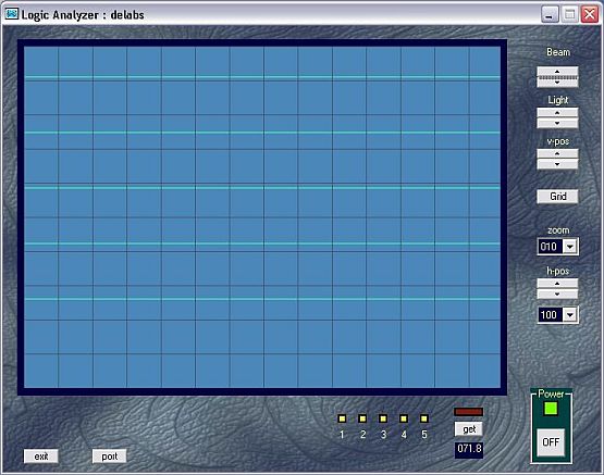
Test Circuit for Logic Analyzer software - del20006
This is a Test Circuit for Logic Analyzer software, with the Simple port circuit. The VB Logic Analyzer works, but is just an example program to test and learn.The speed at which the logic state changes say like 10 M Hz while probing even a PIC or 89C51, is too fast for this circuit. For that, the incoming data has to be spooled or stored in RAM at real time, by the external Hardware itself.
Logic Analyzer on Computer
As this is a Parallel Port Interface, an Embedded High Speed Digital RAM Storage of Multiple Logic input Channels with Signal Conditioning in the front end, could do the job.
This is the minimum, if you want to program the rest of the instrument on Computer Software. Here is one you can see from Bitscope using USB or Ethernet,

Test Circuit for Logic Analyzer software - del20006
To view circuit click the Link of PNG or PDF, The PNG Image can be Drag Scrolled with Mouse.
The vb programs in this page works well on xp-p4 and may not work well on win98-P2. I just also made a sketch of a Logic Spooler for 10MHz Logic Analyzer, this is just a design idea for experts to improve upon.
The design source is here 20006.zip. The Logic Analyzer Program dla_demo.zip . Demo Logic Analyzer 100KHz VB6 program with source code. example to get fast time in uS as vb timer min.1ms is here perftmr.zip.
An Oscilloscope Simulation I made - This is a Toy Scope or a waveform display which i will integrate with my other tutors to display AC points in place of voltmeters. Presently you can play with it. Power On and keep pressing the demo button give a few seconds between presses, to see all the waveforms stored. Tweak the four pots all you want, to understand something of this ancient electricity visualization apparatus.
Load an equation of your own and see it as a waveform on this web scope. Paste a Formula in the Equation text box, load it, it will be rendered as waveform on scope.
...
...
...
...
...
delabs Technologies
20th Mar 2020
...
Disclaimer and Terms of usage
The documents, software, tools and links are provided to enhance the ability of an electronics student, hobbyist or professional by sharing information. The information, links etc. should be used by the website visitor, at his or her own risk and responsibility. There may be concept, design and link errors in the pages.
Creative Work, ideas and documents of delabs can be used for Product Design and Development by R&D Engineers, Hobbyists, Students and even firms for creating useful products. These cannot be used for reprint, replication or publishing online or offline.

