
delabs circuits
Electronic Engineering Schematics
Input Module - J and K Thermocouple with 4-20 mA
This input module converts J, K Thermocouple and 4-20 mA Inputs
to 0-2V Full Scale. These can be used for any voltage/current
inputs too. The RTD module can be modified more easily for
Voltage inputs. The control output can be On-Off or 4-20
mA/Proportional with another card. The 4-20mA I/O STC1000I is
not complete in documentation.12-Bit, 4-20mA Loop-Powered System
This is a Input Signal Conditioning Card for the Temperature controller. The voltage levels from sensors are either too low or need to be translated in level and span. Then for greater accuracy some linearization methods have to be used for a more precise reading. This also increases the cost. The circuits here do no cover the linearization see others in this and my related pages.
The step or segment linearization can be done by transistor, diode or CMOS switches to accomplish varying attenuation/gain for stages of the curve or voltage levels. In Microcontroller systems it can be done by lookup tables or math.
Using Thermocouple with DMM or DVM
In some older digital systems without a MCU, the A to D drives the address of an Eprom Array to get a Digital Data for Display, as a linearized Reading. This Corrected Data was in turn made into analog using a D/A and then on to a Chart Recorder. This was a Logic only System of the early days. Microprocessor systems was expensive, power consuming and use to frighten people by getting lost in loops or a short nap.(they have fixed that, make sure you code properly).

This is the main Schematic Diagram of the Standard J and K Thermocouple Signal Conditioning Module.
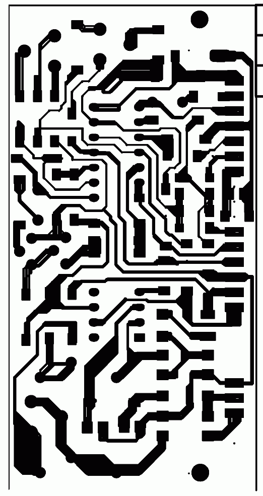
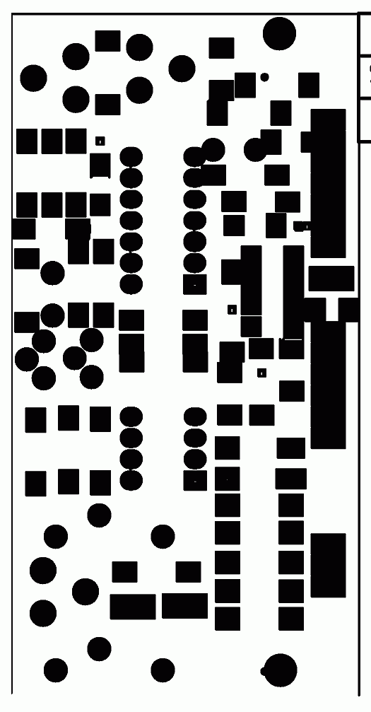
The Circuits and Pcb layouts are below. PNG images can be
Viewed, If you want to build it take a paper print using the
PDF copies also below. The PCB Layouts may need to be scaled
to get usable PCBs.
Derivative Modules from Same Card
J-K Proportional Type - This is the same as above with some spare components used for configuring a proportional controller also with the proportional card. The documentation is not complete and may not be easy for a newbie.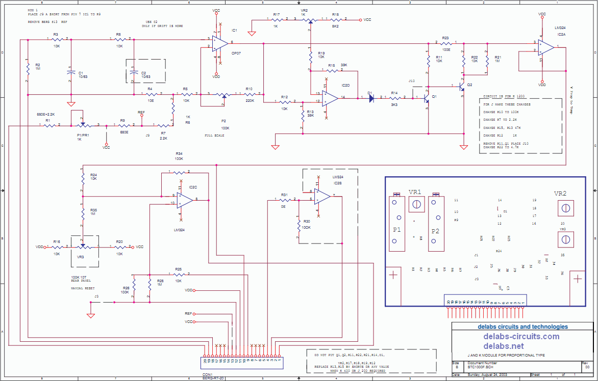
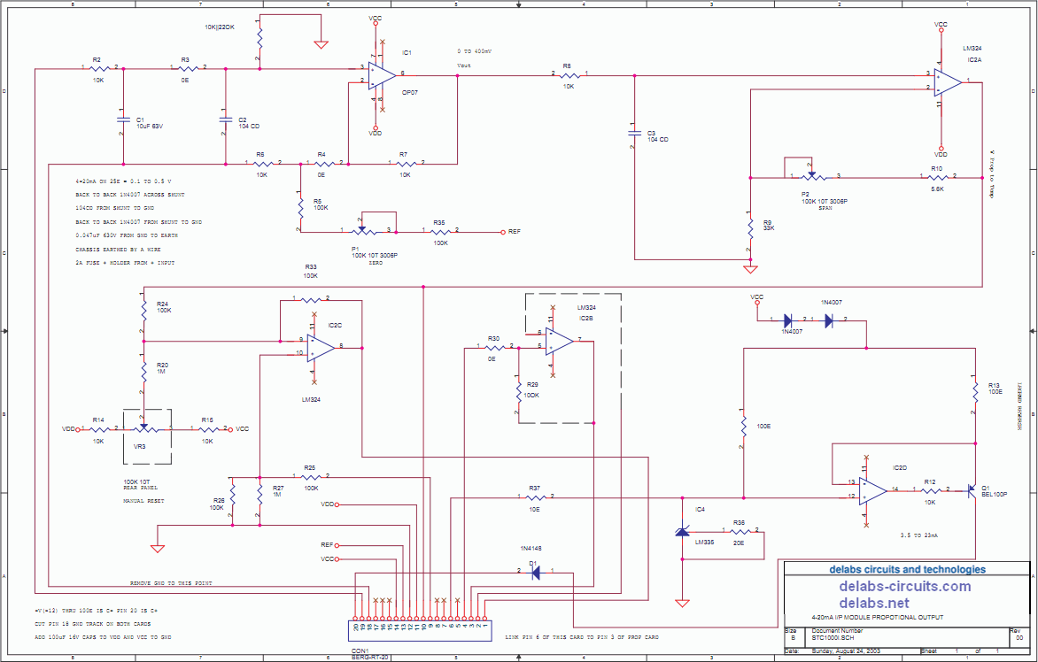
4-20mA In-Out Module - This can be configured as a Current or Voltage Input Module. The shunts or dividers must be put externally near terminal block must be 1% MFR Resistors in Series/Parallel. Current should not heat up R.
The attenuators is also sometimes external, when you have a voltage like 100V from tacho, damping too. AC Voltages are also to be rectified and attenuated near terminal block. Zeners for protection. Then this can be used for AC voltage control for use in Servo Controls.
This also has a Proportional Current or Voltage output for a Strip Chart Recorder, Data Logger or to report to the Supreme SCADA system.
PDF Schematics of Modules
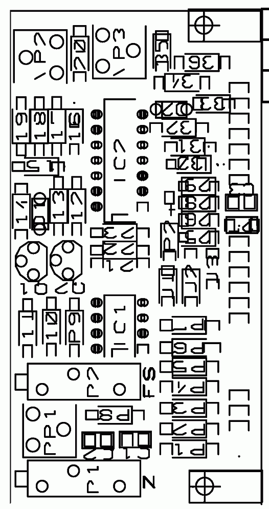
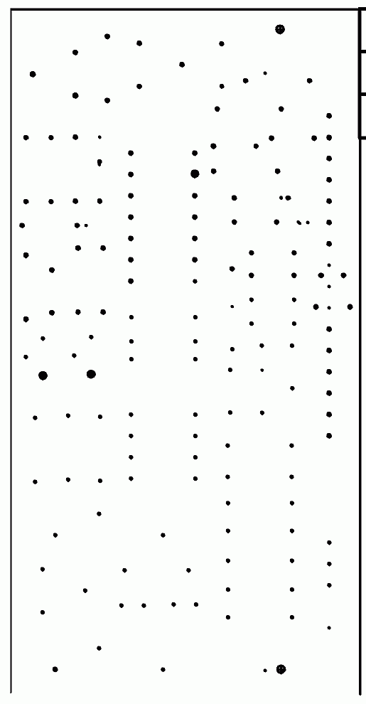
PCB Cards of Input Module
...
...
...
...
...
delabs Technologies
20th Mar 2020
...
The documents, software, tools and links are provided to enhance the ability of an electronics student, hobbyist or professional by sharing information. The information, links etc. should be used by the website visitor, at his or her own risk and responsibility. There may be concept, design and link errors in the pages.
Creative Work, ideas and documents of delabs can be used for Product Design and Development by R&D Engineers, Hobbyists, Students and even firms for creating useful products. These cannot be used for reprint, replication or publishing online or offline.