Non-Inverting Amplifier - Op-Amp Circuits
This High-Input Impedance configuration is commonly used in
front end of sensor signal conditioner and Meters. This page
Includes an Interactive Tutorial with Simulated Meters and
Potentiometers, demonstrating how a Non-Inverting Operational
Amplifier functions. SPICE
Analog Simulation Program TINA
The input impedance of this module is very high, if U1 is
OP07 it is in mega ohms, use CA3140 or LF356 fet input opamps
to get 1 tera ohm input impedance, but for high gains OP07 is
better as it is ultra low offset, this is a good amplifier for
sensor outputs, as in a DC Circuit.
Linear Circuit Design Handbook - Hank Zumbahlen
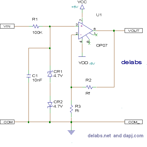
The zener diodes protect the opamp inputs, R1 limits current
during high voltage inputs and R1 and C1 form a filter to
remove ac components C1 should be a plastic type as ceramic
and electrolytic caps are leaky. A large C1 will slow the
response time, the sum of Ri + Rf should be greater than 5k so
that output is not loaded. also do not connect output to
voltages more than vcc/vdd it will blow Opamp.

Vout = Vin * (Rf + Ri) / Ri
Interactive Tutorials using Virtual Electronic ComponentsSlide the Potentiometers just like you would operate a Sliding Control. Drag the Knob on Pot to increase or decrease the resistance. The Resistance is shown is blue letters and dynamically alters value as you slide the pot.
Dual Polarity Analog Output Op-Amps
The mV Source is varied by just moving mouse pointer over the two buttons, no clicking. This reduces finger strain and also you have a long lasting mouse. The mV buttons are special, the variation picks up speed if you let the mouse pointer remain on the button. This is Ramp-up and Ramp-down. This enables you to set it faster with just two buttons.
Use the "iframe" part in this Non-Inverting Op-Amp xml code
Finally you have a DVM a Digital Volt Meter that just Displays the Voltage at any Point, this readout value has to be noted down
These are various web widgets i developed a decade ago. These were tutorials in Electronics and Technology. It also demonstrates usability issues in small devices and using JS-CSS-Ajax in a Innovative way to make GUI dynamic, interactive and contextual. Some of the Ideas were the first of its kind in the GUI design.
More Opamp Simulations...
...
...
...
...
delabs Technologies
20th Mar 2020
...
The documents, software, tools and links are provided to enhance the ability of an electronics student, hobbyist or professional by sharing information. The information, links etc. should be used by the website visitor, at his or her own risk and responsibility. There may be concept, design and link errors in the pages.
Creative Work, ideas and documents of delabs can be used for Product Design and Development by R&D Engineers, Hobbyists, Students and even firms for creating useful products. These cannot be used for reprint, replication or publishing online or offline.

